Section 14.11 Graphic Transformations
As described in Graphic Object Position and Size, each Shape object may be moved and sized using methods such as setLocation(...) and setSize(...). This approach to moving and resizing Shapes has limitations, including the inability to rotate a Shape object, including Text. Consider for a moment how you might draw an oval rotated at a 45° angle. This is not possible using setLocation(...) and setSize(...). Fortunately, there is another way.
Most 2-D computer graphics systems implement a form of linear 2-D geometric transformations known as affine transformations, and include operations such as scale, rotate, and translate. This class of transformations provides a way to modify a shape while preserving its essential nature, e.g. points remain points and parallel lines remain parallel. The easiest way to understand how 2-D transformations work in computer graphics is to imagine that each and every object has its own coordinate system. As described in DoodlePad Drawing Model, when a new DoodlePad Shape object is created its coordinate system is defined with its origin in the upper left corner of the Pad window: x-coordinate values increasing from left to right, y-coordinate values increasing from top to bottom, and distances measured in pixels. Geometric transformation operations give you the ability to move and modify the coordinate system of each and every Shape object independently, with respect to a master coordinate system of the Pad window. For example, it is possible to create two Rectangle Shapes, both with their location set to (0, 0), but appearing at different parts of the Pad. If the coordinate system of one Rectangle is translated to another part of the Pad, then the two Rectangle Shapes would not be drawn at the same location in spite of the fact that they had the same x- and y-coordinate values.
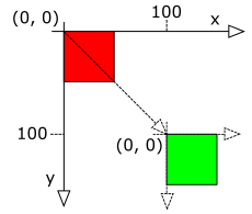
For example, the image on the right depicts two Rectangle Shapes, both with dimensions 50 pixels × 50 pixels and coordinates x=0, y=0. One Rectangle has a red fill and the other has a green fill. The difference between the two Shapes is that the green Rectangle has been transformed by translating it to the location (100, 100). In other words, the origin of the green Rectangle’s coordinate system has been moved (translated) to (100, 100). The green Rectangle’s coordinates (0, 0) are at the same screen location as the red Rectangle’s coordinates (100, 100). In spite of the fact that both Rectangles have identical dimensions and location with respect to their own coordinate systems, they are drawn at different parts of the Pad due to the fact that the green Rectangle’s coordinate system was translated from its default value.
Subsection 14.11.1 Translate
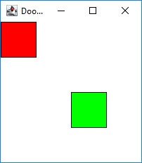
As suggested by the terminology used in the previous example, the coordinate system of a Shape may be moved in the x- and y-directions by invoking a Shape object’s translate(...) method. The translate(...) method takes two double arguments. The first indicates how far to move the Shape’s coordinate system in the x-direction, and the second indicates how far to move the Shape’s coordinate system in the y-direction. The following example program implements the previous red/green Rectangle example using DoodlePad. The class constructor creates two Rectangle objects with identical location and dimension values, but different fill colors. Following this, only the green Rectangle is translated by (100, 100) by executing the statement grnRect.translate(100, 100). Because the starting location of the green Rectangle is (0, 0), after the translation by (100, 100), the new coordinates for the origin of the green Rectangle is (100, 100). The image on the right illustrates the result of executing the following example program.
// Transform1.java
import doodlepad.*;

public class Transform1 {
    private Rectangle redRect;
    private Rectangle grnRect;

    public Transform1() {
        // Two Rectangles with identical location and dimensions
        redRect = new Rectangle(0, 0, 50, 50);
        grnRect = new Rectangle(0, 0, 50, 50);

        // Set fill colors
        redRect.setFillColor(255, 0, 0);
        grnRect.setFillColor(0, 255, 0);

        // Translate the green Rectangle only
        grnRect.translate(100, 100);
    }

    public static void main(String[] args) {
        Transform1 myTransform1 = new Transform1();
    }
}
Transform1.javaSubsection 14.11.2 Scale
The second transformation is scale(...). In effect, a scale(...) transformation zooms in or zooms out on the coordinate system of an object. For example, invoking the scale(...) method with an argument of 2 essentially zooms in by a factor of 2. The coordinate x=50 of the unscaled coordinate system will move to a screen location where x=100 used to be located. Similarly, if a coordinate system is scaled by 0.5, the coordinate x=50 in the unscaled coodinate system will move to a screen location where x=25 used to be located. The same arguments apply to the y-coordinate of the coordinate system. When a shape’s coordinate system is scaled by a number greater than 1, the effect is to increase the size or zoom in on the shape, thus drawing it larger with respect to other shapes with unscaled coordinate systems. With a scale factor less than 1, the effect is to reduce the size or zoom out on a shape as compared to other shapes with unscaled coordinate systems.
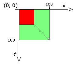
The scale(...) transformation comes in different forms. Thus far we have assumed that the scale factor is applied equally to the x- and y-axes, but this is not necessary. Different scale factors may be applied to the x- and y-axes, and certain overloads of the scale(...) method permit different scale factors for each axis. Also note that when the axes of a Shape’s coordinate system are modified due to a scale(...) transformation, by default all changes are performed around the origin (0, 0). That is to say, all points in the scaled coordinate system will appear to move, except (0, 0). The origin remains fixed, unless a special overload of the transformation is applied. The Shape class implements four overloads of the scale(...) method to account for all these options. The first option is scale(double factor) that takes one scale factor applies it to both the x- and y-axes around the origin (0, 0). The second option is scale(double xFactor, double yFactor) in which the separate scale factors may be applied to each axis. The third option is scale(double factor, double xCenter, double yCenter) in which the same scale factor is applied to both axes, but the scale is applied around the point (xCenter, yCenter) instead of (0,0). This is convenient when a point other than the origin should remain fixed, for example when you want to grow or shrink the size of a shape at its current location. The fourth option is scale(double xFactor, double yFactor, double xCenter, double yCenter) in which independent scale factors are to be applied and a point other than the origin should remain fixed.
Applying the scale transformation is a very convenient way to change the size of an object, but the outcome may not be what you expect. When a coodinate system is scaled, everything that is drawn is scaled, including a Shape’s stroke width. Consider a Shape drawn with a stroke width of 1. After applying a scale transformation of 2 to the Shape’s coodinate system, the Shape with the scaled coordinate system will appear to be drawn with stroke width of 2. From the perspective of the scaled Shape, the stroke width is 1. But when compared to Shapes with unscaled coordinate systems, the stroke will appear to have a width of 2. Often, this is not the desired outcome.
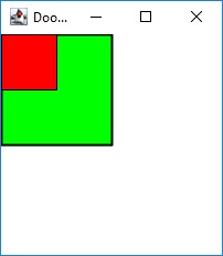
Once again, consider our red and green Rectangle shapes, both with dimensions 50 × 50. After applying a scale factor of 2 to the green Rectangle, the width and height of the green rectangle doubles. Note that the total area of the Rectangle quadruples. The following example program Transform2 demonstrates the result.
// Transform2.java
import doodlepad.*;

public class Transform2 {
    private Rectangle redRect;
    private Rectangle grnRect;

    public Transform2() {
        // Two Rectangles with identical location and dimensions
        grnRect = new Rectangle(0, 0, 50, 50);
        redRect = new Rectangle(0, 0, 50, 50);

        // Set fill colors
        redRect.setFillColor(255, 0, 0);
        grnRect.setFillColor(0, 255, 0);

        // Scale the green Rectangle only
        grnRect.scale(2);
    }

    public static void main(String[] args) {
        Transform2 myTransform2 = new Transform2();
    }
}
Transform2.javaSubsection 14.11.3 Rotate
The last transformation method is rotate(...). The rotate(...) method takes an angle argument in degrees and rotates the coordinate system of a Shape around the origin (0, 0) by that angle in a clockwise direction. You may be accustomed to the rotation of an angle to be in the counter-clockwise direction. In fact, this is not inconsistent with 2-D computer graphics. Because the drawing model of 2-D graphics inverts the orientation of the y-axis, the rotation angle appears to proceed in the clockwise direction.
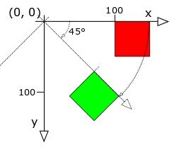
As with scale(...), there are multiple overloads of the rotate(...) method. The first overload is rotate(double angle) which expects a single argument indicating the angle in degrees to rotate the coordinate system of a Shape object. The rotate occurs around the origin (0, 0). A second overload is rotate(double angle, double xCenter, double yCenter). This option allows you to set the point about which the Shape’s coordinate system is rotated. This is useful when you want to rotate an object in place.
In the example program Transform3 our red and green Rectangle are located at (100, 0). We rotate our green Rectangle’s coordinate system by 45° while the red Rectangle’s coordinate system remains unchanged. Note how the coordinate system is rotated around the origin (0, 0).
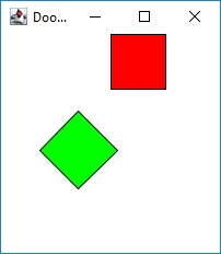
// Transform3.java
import doodlepad.*;

public class Transform3 {
    private Rectangle redRect;
    private Rectangle grnRect;

    public Transform3() {
        // Two Rectangles with identical location and dimensions
        grnRect = new Rectangle(100, 0, 50, 50);
        redRect = new Rectangle(100, 0, 50, 50);

        // Set fill colors
        redRect.setFillColor(255, 0, 0);
        grnRect.setFillColor(0, 255, 0);

        // Rotate the green Rectangle only
        grnRect.rotate(45);
    }

    public static void main(String[] args) {
        Transform3 myTransform3 = new Transform3();
    }
}
Transform3.javaSubsection 14.11.4 Reset
You are free to apply as many transformations as you like, in any order. All transformations are cumulative; you will see only the final accumulated result. For example, if we create a Shape object, translate it by (50, 50), and then translate it by (50, 50) a second time, the Shape’s coordinate system will have its origin located at (100, 100). Use the Shape’s reset() method to set all transformations back to their default values.
Subsection 14.11.5 Pad Transformations
In addition to Shape objects, transformations may be applied to a Pad object. In fact, the same transformation methods and their overloads may be applied to a Pad object in a manner identical to a Shape object. Furthermore, when the Pad’s coordinate system is transformed, the transformations are applied to all Shapes drawn on the Pad because Shape coordinate systems are relative to their Pad’s coordinate system. When you are interested in zooming or rotating an entire diagram rather than an individual Shape object, applying transformations to the Pad object is a much simpler way to go.
